假装网络工程师17——初识BGP
一、背景介绍
BGP是一种多用于运营商之间的网络协议类型,他与IGP不同的地方(主要指IGP中的ospf协议)在于它是一种距离矢量型的协议,所以路由器之间传递的为路由表,而运行商选择BGP协议的原因在于IGP协议无法容纳公网上数量巨大的路由条目
二、BGP的工作模式
BGP作为一种应用层协议,工作在7层,类似于ospf协议,运行BGP协议的路由器之间需要建立对等体关系。在ospf中,只有直连路由器之间才能建立邻居关系(因为TTL=1),而在BGP协议中,建立对等体关系的路由器不是必须直连(IBGP中TTL=255;虽然EBPG中TTL=1,但可以修改),两个路由可达的路由器之间就可以建立对等体关系,如下图所示,RB与RE之间尽管没有直连,但仍可以建立对等体关系,在IBGP中路由器之间需要建立全网状对等体关系,所以IBGP的对等体数量为n*(n-1)/2  上图中RB与RE要建立对等体,首先就需要相互之间路由可达,这就需要借助IGP(ospf等)协议来实现,从这个角度来看,可以说BGP是建立在IGP之上的协议
三、BGP的分类
BGP按照工作的区域,可以分为IBGP与EBGP两种,在同一个as内运行BGP协议的路由器之间是IBGP协议,不同as之间的路由器采用EBGP协议,as号有65535个,类似于私有ip地址64512~65535这1024个as为私有as号,BGP的as号,相当于BGP的进程号,不同于ospf,每个路由器上只能启动1个BGP进程,即每个路由器只能属于1个as,BGP按照工作的区域又可以分为:
1.IBGP
在同一as内建立BGP对等体的路由器相互之间是IBGP,由于BGP是一种距离矢量行协议(DV),所以防环成为必须要考虑的事情,在IBGP中,采用“水平分割法”来进行防环,即:在同一个as内,路由器B从对等体路由器A处学到的路由,不会再发给本as内其他的IBGP对等体,IBGP通常使用环回口建立对等体关系
2.EBGP
EBPG作用于不同as之间,通过AS_PATH属性防环,当一个路由器发现传递过来的属性中包含自己的AS_PATH编号,则会拒绝接收。从EBGP学习到的路由会自动同步给其他IBGP和EBGP对等体,且被同步的路由器不会更改下一跳地址,对于IBGP对等体,需要手动修改下一跳地址
四、实验拓扑
本次实验的拓扑如下图所示,其中,as2345中跑ospf协议,BGP建立在ospf基础之上,ospf在宣告时,R2的g0/0/0接口与R5的g2/0/0接口不宣告进ospf(因为要做EBGP,对方不会相应ospf的hello报文),R2与R5的lo1接口也不宣告进ospf(留作IBGP起源地址)R2与R5建立IBGP对等体关系 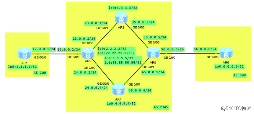 这样整个拓扑结构梳理为以下几点:
- R1、R2之间,R5、R6之间建立EBGP对等体
- R2、R3、R4、R5之间建立ospf邻居
- R2、R5之间建立IBGP对等体
- R3、R4现阶段没有运行BGP协议
为实现以上条件,R1上的配置如下:
[R1]bgp 100 [R1-bgp]router-id 1.1.1.1[R1-bgp]peer 12.0.0.2 as-number 2345[R1-bgp]peer 12.0.0.2 connect-interface g0/0/0R2上的配置如下:
[R2]ospf 1 router-id 2.2.2.2[R2-ospf-1]area 0[R2-ospf-1-area-0.0.0.0]network 2.2.2.2 0.0.0.0[R2-ospf-1-area-0.0.0.0]network 23.0.0.2 0.0.0.0[R2-ospf-1-area-0.0.0.0]network 24.0.0.2 0.0.0.0[R2]bgp 2345[R2-bgp]router-id 2.2.2.2[R2-bgp]peer 12.0.0.1 as-number 100[R2-bgp]peer 12.0.0.1 connect-interface g0/0/0[R2]bgp 2345[R2-bgp]peer 5.5.5.5 as-number 2345[R2-bgp]peer 5.5.5.5 connect-interface lo0R3上的配置如下:
[R3]ospf 1 router-id 3.3.3.3[R3-ospf-1]area 0[R3-ospf-1-area-0.0.0.0]network 23.0.0.3 0.0.0.0[R3-ospf-1-area-0.0.0.0]network 35.0.0.3 0.0.0.0[R3-ospf-1-area-0.0.0.0]network 3.3.3.3 0.0.0.0R4上的配置如下:
[R4]ospf 1 router-id 4.4.4.4[R4-ospf-1]area 0[R4-ospf-1-area-0.0.0.0]network 24.0.0.4 0.0.0.0[R4-ospf-1-area-0.0.0.0]network 45.0.0.4 0.0.0.0[R4-ospf-1-area-0.0.0.0]network 4.4.4.4 0.0.0.0R5上的配置如下:
[R5]ospf 1 router-id 5.5.5.5[R5-ospf-1]area 0[R5-ospf-1-area-0.0.0.0]network 2.2.2.2 0.0.0.0[R5-ospf-1-area-0.0.0.0]network 23.0.0.2 0.0.0.0[R5-ospf-1-area-0.0.0.0]network 24.0.0.2 0.0.0.0[R5]bgp 2345[R5-bgp]router-id 5.5.5.5[R5-bgp]peer 56.0.0.6 as-number 600[R5-bgp]peer 56.0.0.6 connect-interface g2/0/0[R5]bgp 2345[R5-bgp]peer 2.2.2.2 as-number 2345[R5-bgp]peer 2.2.2.2 connect-interface lo0R6上的配置如下:
[R6]bgp 600[R6-bgp]router-id 6.6.6.6[R6-bgp]peer 56.0.0.5 as-number 2345[R6-bgp]peer 56.0.0.5 connect-interface g0/0/0以R2为例,此时能看到R2与R1和R5都已建立了BGP对等体关系
<R2>dis bgp peer BGP local router ID : 2.2.2.2 Local AS number : 2345 Total number of peers : 2 Peers in established state : 2 Peer V AS MsgRcvd MsgSent OutQ Up/Down State PrefRcv 5.5.5.5 4 2345 47 49 0 00:45:40 Established 0 12.0.0.1 4 100 63 63 0 01:01:53 Established 0<R2>1.起源IBGP路由
此时R2与R5之间已经建立了对等体,在R2与R5的路由器上面将lo1接口的地址宣告进IBGP,即起源地址。起源的路由必须是本路由器上存在的路由条目,且掩码位数必须与路由条目中保持一致。起源的地址只要存在于本路由器的路由表中即可,可以是非直连,一半情况是在边界路由器上起源本as内全部路由地址
[R2]bgp 2345[R2-bgp]network 22.22.22.22 32[R5]bgp 2345[R5-bgp]network 55.55.55.55 32以R2为例,此时在R2的BGP路由表中已经能看到通往55.55.55.55/32的路由下一跳是5.5.5.5
<R2>dis bgp routing-table BGP Local router ID is 2.2.2.2 Status codes: * - valid, > - best, d - damped, h - history, i - internal, s - suppressed, S - Stale Origin : i - IGP, e - EGP, ? - incomplete Total Number of Routes: 2 Network NextHop MED LocPrf PrefVal Path/Ogn *> 22.22.22.22/32 0.0.0.0 0 0 i *>i 55.55.55.55/32 5.5.5.5 0 100 0 i同时,R2路由器会将将最优的BGP路由条目加载到自己的路由表中,R5上也是类似结果,此处不再赘述
<R2>display ip routing-table protocol bgp Route Flags: R - relay, D - download to fib------------------------------------------------------------------------------Public routing table : BGP Destinations : 1 Routes : 1 BGP routing table status : <Active> Destinations : 1 Routes : 1Destination/Mask Proto Pre Cost Flags NextHop Interface 55.55.55.55/32 IBGP 255 0 RD 5.5.5.5 GigabitEthernet2/0/0 IBGP 255 0 RD 5.5.5.5 GigabitEthernet0/0/1BGP routing table status : <Inactive> Destinations : 0 Routes : 02.IBPG的路由黑洞
做完上述操作后,从R5的路由表中也能看到去往22.22.22.22/32网段的地址
<R5>display ip routing-table protocol bgp Route Flags: R - relay, D - download to fib------------------------------------------------------------------------------Public routing table : BGP Destinations : 1 Routes : 1 BGP routing table status : <Active> Destinations : 1 Routes : 1Destination/Mask Proto Pre Cost Flags NextHop Interface 22.22.22.22/32 IBGP 255 0 RD 2.2.2.2 GigabitEthernet0/0/1 IBGP 255 0 RD 2.2.2.2 GigabitEthernet0/0/0BGP routing table status : <Inactive> Destinations : 0 Routes : 0但此时,你会发现在R2上无法ping通R5,反过来一样
<R2>ping -a 22.22.22.22 55.55.55.55 PING 55.55.55.55: 56 data bytes, press CTRL_C to break Request time out Request time out Request time out Request time out Request time out其原因就是尽管R2和R5之间建立了IBGP对等体,但数据包无法直接从R2“飞”到R5 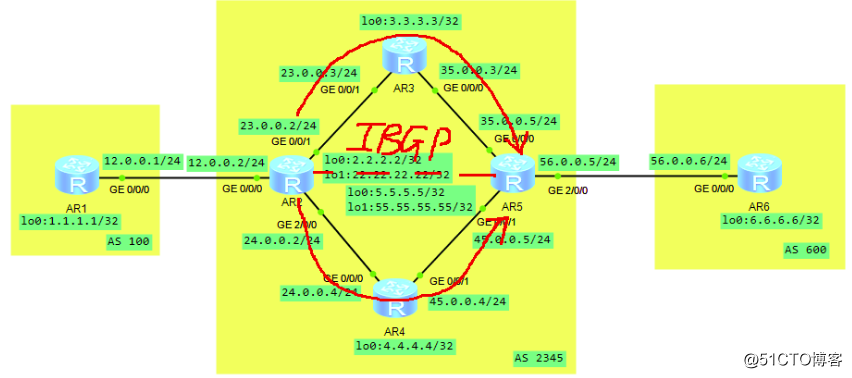 这一点在路由表中能够清楚地看到,在R2路由器表中能看到目的地址是55.55.55.55/32的路由,下一跳为5.5.5.5,而去往5.5.5.5/32段,下一跳是R3或者R4
<R2>dis ip routing-table Route Flags: R - relay, D - download to fib------------------------------------------------------------------------------Routing Tables: Public Destinations : 21 Routes : 22 Destination/Mask Proto Pre Cost Flags NextHop Interface 55.55.55.55/32 IBGP 255 0 RD 5.5.5.5 GigabitEthernet2/0/0 5.5.5.5/32 OSPF 10 2 D 24.0.0.4 GigabitEthernet2/0/0 OSPF 10 2 D 23.0.0.3 GigabitEthernet0/0/1而此时R3或者R4路由器上根本没有22.22.22.22/32的源地址,所以数据包在到达R3或者R4路由器上时,直接被丢弃
<R3>dis ip routing-table Route Flags: R - relay, D - download to fib------------------------------------------------------------------------------Routing Tables: Public Destinations : 16 Routes : 17 Destination/Mask Proto Pre Cost Flags NextHop Interface 2.2.2.2/32 OSPF 10 1 D 23.0.0.2 GigabitEthernet0/0/1 3.3.3.3/32 Direct 0 0 D 127.0.0.1 LoopBack0 4.4.4.4/32 OSPF 10 2 D 35.0.0.5 GigabitEthernet0/0/0 OSPF 10 2 D 23.0.0.2 GigabitEthernet0/0/1 5.5.5.5/32 OSPF 10 1 D 35.0.0.5 GigabitEthernet0/0/0 23.0.0.0/24 Direct 0 0 D 23.0.0.3 GigabitEthernet0/0/1 23.0.0.3/32 Direct 0 0 D 127.0.0.1 GigabitEthernet0/0/1 23.0.0.255/32 Direct 0 0 D 127.0.0.1 GigabitEthernet0/0/1 24.0.0.0/24 OSPF 10 2 D 23.0.0.2 GigabitEthernet0/0/1 35.0.0.0/24 Direct 0 0 D 35.0.0.3 GigabitEthernet0/0/0 35.0.0.3/32 Direct 0 0 D 127.0.0.1 GigabitEthernet0/0/0 35.0.0.255/32 Direct 0 0 D 127.0.0.1 GigabitEthernet0/0/0 45.0.0.0/24 OSPF 10 2 D 35.0.0.5 GigabitEthernet0/0/0 127.0.0.0/8 Direct 0 0 D 127.0.0.1 InLoopBack0 127.0.0.1/32 Direct 0 0 D 127.0.0.1 InLoopBack0127.255.255.255/32 Direct 0 0 D 127.0.0.1 InLoopBack0255.255.255.255/32 Direct 0 0 D 127.0.0.1 InLoopBack03.同步与建立全网状对等体
上述问题的原因在于,R3与R4在自身没有22.22.22.22/32和55.55.55.55/32路由的情况下,将IBGP学到的路由发送给了其他对等体。为了解决这个问题,早期要求只有路由器通过IGP学到了相同的BGP路由后,才能将BGP路由发送给其他对等体。即路由器通过BGP学习到的所有路由都要保证通过IGP也学习到,否则它不向其他对等体发送通过BGP学习到的路由条目。但前文说过,BGP的路由数量太大,IGP无法承载,所以现在所有路由器上将这个限制默认关闭
[R3-bgp]dis thisipv4-family unicast undo synchronization另外一种解决方法是R3、R4路由也建立对等体关系,又由于IBGP的水平分割机制,所以就能解释为什么IBGP对等体需要全网状建立,根据n*(n-1)/2的原则,本例中共需建立6个IBGP对等体,除去已建立对等体的R2--R5,还需要建立的对等体为: R2--R3,R2--R4,R5--R3,R5--R4,R3--R4
[R2]bgp 2345[R2-bgp]peer 3.3.3.3 as-number 2345[R2-bgp]peer 3.3.3.3 connect-interface lo0[R2-bgp]peer 4.4.4.4 as-number 2345[R2-bgp]peer 4.4.4.4 connect-interface lo0[R3]bgp 2345[R3-bgp]peer 2.2.2.2 as-number 2345[R3-bgp]peer 2.2.2.2 connect-interface lo0[R3-bgp]peer 5.5.5.5 as-number 2345[R3-bgp]peer 5.5.5.5 connect-interface lo0[R3-bgp]peer 4.4.4.4 as-number 2345[R3-bgp]peer 4.4.4.4 connect-interface lo0[R4]bgp 2345[R4-bgp]peer 2.2.2.2 as-number 2345[R4-bgp]peer 2.2.2.2 connect-interface lo0[R4-bgp]peer 3.3.3.3 as-number 2345[R4-bgp]peer 3.3.3.3 connect-interface lo0[R4-bgp]peer 5.5.5.5 as-number 2345[R4-bgp]peer 5.5.5.5 connect-interface lo0[R5]bgp 2345[R5-bgp]peer 3.3.3.3 as-number 2345[R5-bgp]peer 3.3.3.3 connect-interface lo0[R5-bgp]peer 4.4.4.4 as-number 2345[R5-bgp]peer 4.4.4.4 connect-interface lo0全网状的IBGP对等体建立完成后,R3和R4路由上就能学习到22.22.22.22/32和55.55.55.55/32路由并放入自己的路由表中
<R3>display ip routing-table protocol bgp Route Flags: R - relay, D - download to fib------------------------------------------------------------------------------Public routing table : BGP Destinations : 2 Routes : 2 BGP routing table status : <Active> Destinations : 2 Routes : 2Destination/Mask Proto Pre Cost Flags NextHop Interface 22.22.22.22/32 IBGP 255 0 RD 2.2.2.2 GigabitEthernet0/0/1 55.55.55.55/32 IBGP 255 0 RD 5.5.5.5 GigabitEthernet0/0/0BGP routing table status : <Inactive> Destinations : 0 Routes : 0此时再去R2上带源ping 55.55.55.55,通信正常
<R2>ping -a 22.22.22.22 55.55.55.55 PING 55.55.55.55: 56 data bytes, press CTRL_C to break Reply from 55.55.55.55: bytes=56 Sequence=1 ttl=254 time=70 ms Reply from 55.55.55.55: bytes=56 Sequence=2 ttl=254 time=40 ms Reply from 55.55.55.55: bytes=56 Sequence=3 ttl=254 time=30 ms Reply from 55.55.55.55: bytes=56 Sequence=4 ttl=254 time=30 ms Reply from 55.55.55.55: bytes=56 Sequence=5 ttl=254 time=30 ms4.修改IBGP路由器下一跳地址
将R1与R6的lo0接口地址起源
[R1]bgp 100[R1-bgp]network 1.1.1.1 32 [R6]bgp 600[R6-bgp]network 6.6.6.6 32此时,在R3和R4上看到去往R1与R6环回口的下一跳是12.0.0.1和56.0.0.6
<R3>display bgp routing-table BGP Local router ID is 35.0.0.3 Status codes: * - valid, > - best, d - damped, h - history, i - internal, s - suppressed, S - Stale Origin : i - IGP, e - EGP, ? - incomplete Total Number of Routes: 4 Network NextHop MED LocPrf PrefVal Path/Ogn i 1.1.1.1/32 12.0.0.1 0 100 0 100i i 6.6.6.6/32 56.0.0.6 0 100 0 600i *>i 22.22.22.22/32 2.2.2.2 0 100 0 i *>i 55.55.55.55/32 5.5.5.5 0 100 0 i由于R3和R4的路由表中并没有这两个网段的路由信息,所以次BGP路由不是最优,不会加载进路由表,R1无法ping通R6。这也印证了EBGP传往IBGP的时候下一跳是自身,不会改变,需要手动在修改R2和R5的下一跳地址
[R2]bgp 2345[R2-bgp]peer 3.3.3.3 next-hop-local [R2-bgp]peer 4.4.4.4 next-hop-local[R2-bgp]peer 5.5.5.5 next-hop-local[R5]bgp 2345[R5-bgp]peer 2.2.2.2 next-hop-local[R5-bgp]peer 3.3.3.3 next-hop-local[R5-bgp]peer 4.4.4.4 next-hop-local修改后再到R3上查看BGP路由表,发现欲望1.1.1.1/32与6.6.6.6/32网段下一跳已经改为as内的边界路由器,BGP路由表为最优,已加载进路由表中
[R3]dis bgp routing-table BGP Local router ID is 35.0.0.3 Status codes: * - valid, > - best, d - damped, h - history, i - internal, s - suppressed, S - Stale Origin : i - IGP, e - EGP, ? - incomplete Total Number of Routes: 4 Network NextHop MED LocPrf PrefVal Path/Ogn *>i 1.1.1.1/32 2.2.2.2 0 100 0 100i *>i 6.6.6.6/32 5.5.5.5 0 100 0 600i *>i 22.22.22.22/32 2.2.2.2 0 100 0 i *>i 55.55.55.55/32 5.5.5.5 0 100 0 i此时R1就可以ping通R6了
<R1>ping -a 1.1.1.1 6.6.6.6 PING 6.6.6.6: 56 data bytes, press CTRL_C to break Reply from 6.6.6.6: bytes=56 Sequence=1 ttl=252 time=70 ms Reply from 6.6.6.6: bytes=56 Sequence=2 ttl=252 time=60 ms Reply from 6.6.6.6: bytes=56 Sequence=3 ttl=252 time=50 ms Reply from 6.6.6.6: bytes=56 Sequence=4 ttl=252 time=50 ms Reply from 6.6.6.6: bytes=56 Sequence=5 ttl=252 time=40 ms